Piccoboard with separate tail ESC
If you are flying the Piccolo with the Piccoboard on 8 cells, you may be having tail motor lifetime problems. This is discussed in the Hints and Tips section of this site, under the topic Tail Motor. Until now, the only cure has been to go to completely separate components and use the JMP HF9 high frequency ESC for the tail. (The heli version HF9 is available in the US from Homefly.com).No longer!
I have discovered a very simple method of connecting the HF9 directly to the both the original Piccoboard and the Piccoboard Plus, bypassing the Piccoboard's tail ESC but retaining the Piccoboard gyro and mixing functions. There is a point on the Piccoboard that carries the decoded rudder channel pulse train with the gyro action and mixer functions mixed in. This point is a positive going pulse of about 4V and thus can be directly applied to the signal input of any conventional ESC. And best of all, it is easily accessible. Since the zero point set function is apparently accomplished after this point, the zero point set feature is dependant on the HF9 or whatever tail ESC you use. It is NOT set by the Piccoboard at this point.
Note that connecting to this point is a rather delicate operation. Do not attempt this if you are not completely comfortable with micro soldering techniques, including the use of a microscope or jeweler's loupe.
All that is required to make this modification is to connect a wire to one side of a component on the Piccoboard. The other end of the wire is equipped with a pin that fits the receptacle on the end of the HF9 signal lead. Additionally, I added two female receptacles (female connectors from a DB-9 computer connector, covered with shrink tubing) to the positive and negative pads on the Piccoboard. With the HF9 fitted with mating connectors, you can switch back and forth from Piccoboard tail ESC to HF9 in seconds.
See the following photographs for details. Since this is a "hacked" modification (ie., without the aid of a schematic), I take no responsibility for any damage. I believe the modification to be safe, but any modification without a careful design study carries some risk. Additionally, I have no idea how well buffered this signal point is, and accidentally connecting it to ground or battery positive could damage something. Finally, if you try this modification, don't forget to insulate the Piccoboard tail motor wires since they are now un-terminated.
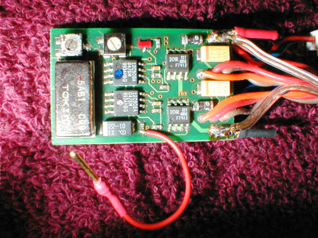
Original version Piccoboard. The red wire is the added signal wire. Note also the two added power connectors at the left side of the board.
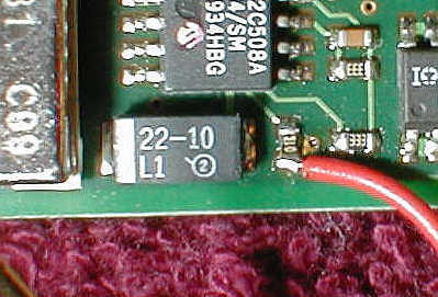
Original version Piccoboard. Closeup, showing the wire connection location. Note that the feedthrough hole just visible under the wire is also usable as a wire attachment point. I elected to use the end of the component because I was having trouble getting solder to wet the pad and was afraid of lifting the foil.
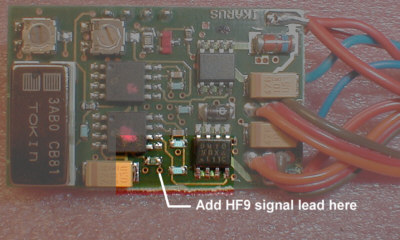
Piccoboard Plus, showing the signal pickoff point. Very similar to the original version Piccoboard.